This post is also available in:
![]() Türkçe (Turkish)
Türkçe (Turkish)
ACS712 Current Sensor
- ACS712 sensor can accurately measure the current passing through the”hall-effect” system.
- “Hall-effect” system measures the current from the magnetic field generated when a current is passed through a core.
- ACS712 can measure both AC and DC current
- ACS712 is quite successful in this matter. However, we must take into account the current value when purchasing this integration. Accordingly, ACS712 has been produced in three types.
- Measures up to 5A
- Measures up to 20A
- Measures up to 30A
- If it is exposed to a current value higher than the above values, the measuring legs will be burned.
- Another feature of the ACS712 is that even if a high current or voltage is present at the ends of the current, it does not transmit to the PIC or MCU, means that there is an insulation inside it so that it does not transmit this high voltage and current further.
- Although it measures with magnetic field, it is not affected by magnet or similar magnetic fields.
- Perhaps the only bad thing is that it gives analog output, so ADC operation will have to be done.
How to Estimate Current with ACS712
- The key for this, of course, is stored in the ACS712 user manual(datasheet).
- The following picture is taken from the user manual. Note that a different value is given for each current.

- According to the above table
- For 5 Amp integration – > 185 mV for 1 Amp
- For 20 Amp integration – > 100 mV for 1 Amp
- For 30 Amp integration – > 66 mV for 1 Amp
- If we calculate for PICs, in PICs generally 10 bits of ADC are found.(210=1024)
- The supply voltage (i.e., the reference voltage) is 5 volts
- Also, according to what we learned from the manual, the ACS712 outputs 2.5 volts when it is at “0” (zero) amperes.
- To summarize the basic principle, looking at these data
- When we substract 2.5 volts from the measured value, every 185mV means 1 amp (for 5 Amps ACS712)
- To calculate,
- For example, we read 550 value from ADC with PIC
- (5/1024)=0,0048828125 this is our ADC value for each voltage
- (5/1024)*550 = 2,685546875 is calculated. This is actually our voltage value.
- As mentioned before we must substract 2.5 volt
- 2,685546875–2,5= 0,185546875 value is received.
- 0,185546875/0,185 =1,002 we receive this result, means that when 550 value is read from ADC, the current pass from ACS712 is 1,002 Amp.( 1 amp 2mA)
- In the example above, why did we divided the value into 0,185 but not into 185? Notice that it is 185 mV, because when we operate in volts we divide mV by 1000 to turn it into Volt.
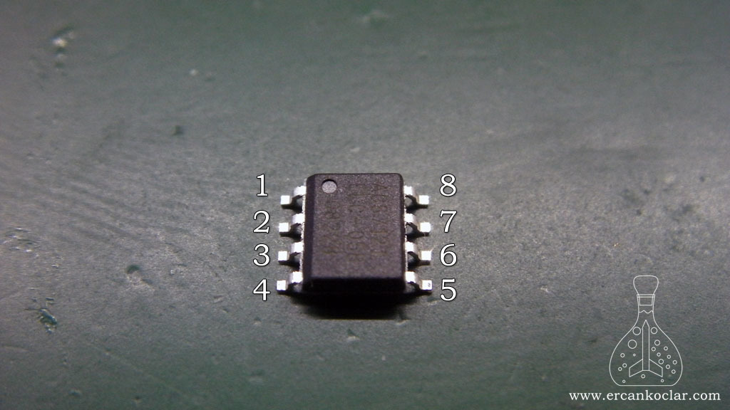
ACS712 Pin Functions
| Number | Name | Description |
| 1 – 2 | IP+ | + pole connected in DC current, there is no difference in – AC current |
| 3 – 4 | IP- | – pole is connected on DC current, – no difference in AC current |
| 5 | GND | Grounding tip |
| 6 | FILTER | Arranges output by connecting external condenser |
| 7 | VIOUT | Analog output tip is connected to MCU or PIC |
| 8 | VCC | Feeding tip is connected+5 volt |
ACS712 Circuit Diagram
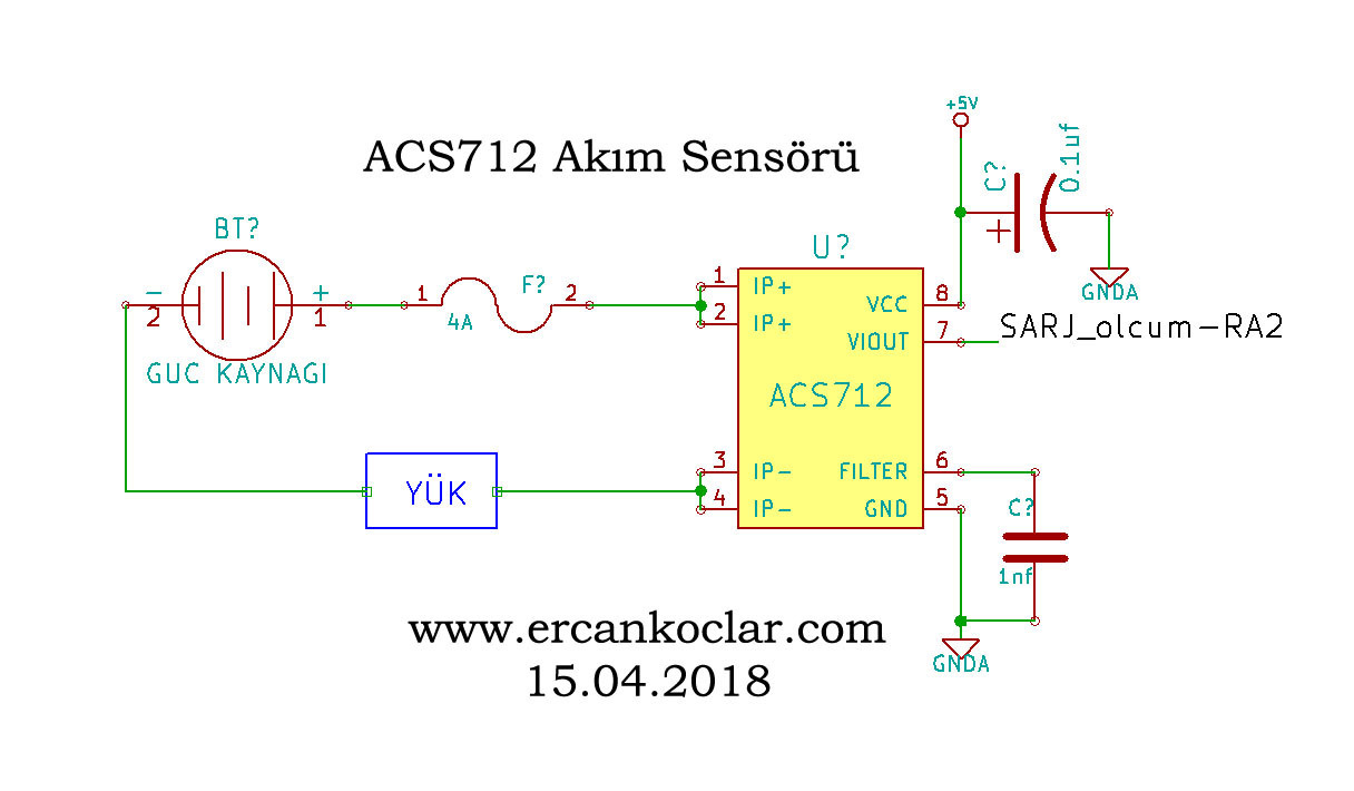
- I used 4 amperes of glass fuse because I use 5 amperes ACS712 in the circuit. If more current than 4 amperes, the fuse could burn and protect the integration
- The measurement tips of the ACS712 are combined. However, if desired, one end can be connected and the other end can be left as spare in case of a possible combustion state.
- The current measurement is done in series as opposed to the volt measurement. For this reason, the power supply and the load (motor-led, etc.) to be connected to it must be connected and completed in series format.
Necessary Materials
- ACS712 integration
- 0.1uF-63V electrolytic condenser
- 1nF polyester condenser
- 4A glass fuse and fuse holder
- SOIC – DIP convertor
Making Circuit
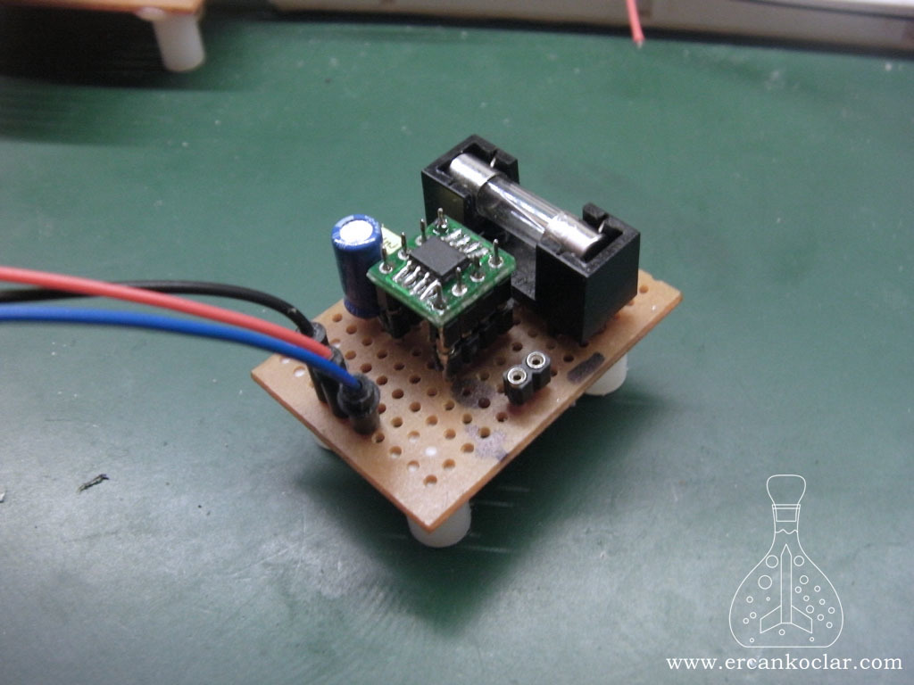
- Since the circuit was made with the purpose of testing, it is built on pertinax
- The 2 outputs on the right are current measurement tips
- 4A glass fuse installed to protect the part
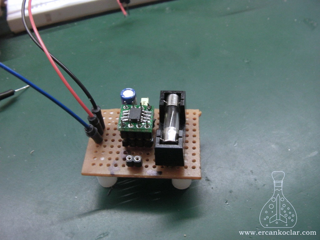
- Tips on the left side are; blue: analog output, red and black: feeding pins. (+ 5v)
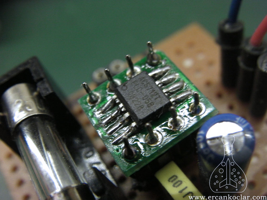
- The pins are soldered with the help of the converter for the integration, since it is SOIC type.
- These types of translators are available in ready format.
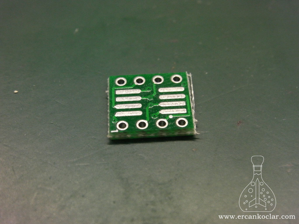
- The above converter is especially useful for test circuits in many studies.
- When converting from SOIC to DIP, the back side is also suitable for narrower type integrations.
- You can look at the following photo to understand the size.
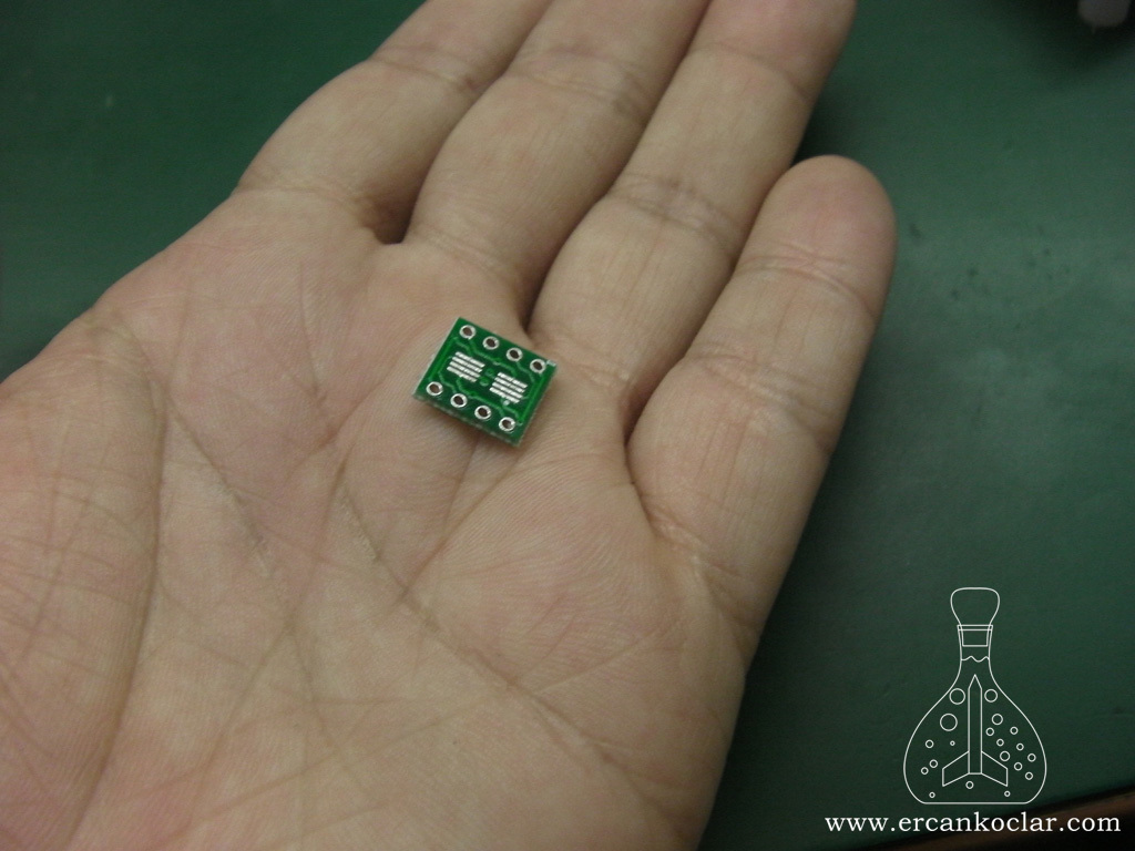
- As you can see, it is a small size and a life-saving piece.
ACS712 MicroC Library
- I wrote a library in MicroC for ACS712 to measure the current, it cannot even be called as a library, it is made up of only one function.
- Because ADC operations are performed, the standard ADC library of MicroC must be added to the project.
- The function returns the value as mA.
- Fluctuation in current measurements is normal. This is due to the sensitivity of the integration.
- Note that, current over 10 amperes are dangerous.
Functions
- There is a single function, which tells us the current in ACS712 as int type mA (milliamps).
–ACS712_AKIM_OLCME Function
Function : unsigned int ACS712_AKIM_OLCME(unsigned char SENSOR_TIPI,unsigned char ANALOG_KANAL)
Purpose : Evaluates current passes from ACS712
Parameters :
- SENOSOR_TIP : It is specified how many amps of ACS712 used. It can only take the following values, otherwise it will return the error code “0” value.
- 5 = 5 amp sensor
- 20 = 20 amp sensor
- 30 = 30 amp sensor
- ANALOG_KANAL : Indicates which adc channel will be measured by the PIC.
Its Usage :
ACS712_AKIM_OLCME(5,4) ;//5 amperes sensor. Reading will be done from AN4
Feedback :
- int type data will be returned as mA(miliamp)
Application of Functions
Pin Identification
sbit ACS712_VERI_PIN at RA5_bit ;               //ACS712 output tip connection pin
sbit ACS712_VERI_PIN_Direction  at TRISA5_bit; //ACS712 output tip connection pin
- You must start writing the code by making the pin idefinitions, otherwise the program will give error.
Reading Current
void  main()
{
    char deger[15];
    unsigned char i=0,j=1;
    unsigned int ercan=0;


    ADCON1=0b00000001;
    CMCON=7;

   ADC_Init();//PIC adc operations must be started
   delay_ms(100);
   SAP1024_INIT(240,128,6);//SAP1024B GLCD screen identification
   delay_ms(100);

while(1)
 {
   ercan = ACS712_AKIM_OLCME(5,4) ;

   inttostr(ercan,deger);
   SAP1024_YAZI_YAZMA(10,10,deger);//the read values will be printed on GLCD

   delay_ms(500);// Does reading in every 1/2 second
 }
}
- ADC setting was done according to PIC
- We talked about analog signal input with ADC_Inıt
- We stated that it has”ACS712_AKIM_OLCME(5,4)” function and 5 amp sensor, and reading must be done from AN4 port
- We said that GLCD values must be written in 1/2 second intervals.
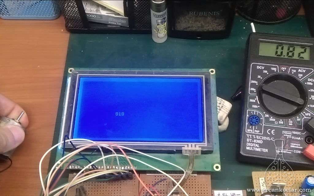
Experiment Video
Result
- You learned the theoretical knowledge of calculation about ACS712 operation.
- With this information you can write your own library, or you can look at the open source code I wrote.
- It is normal for the measurement to fluctuate because the current does not actually flow in a straight line, it will rise and fall instantaneously. The reflection on the screen is due to the sensitivity of the ACS712.
- The value seen on the video is mA. ( 1 A = 1000mA) – The gauge is set to the amper
- You can ask your questions in “Q&A” forum.
Library Files
- ACS712 Current Sensor MikroC Library – OPEN SOURCE CODE – (Click to Purchase)
- ACS712 Current Sensor MikroC Library – .mcl – (FREE)
Bağlantıyı Görmek İçin Giriş Yapın ya da Ücretsiz Üye Olun
References
This post is also available in:
![]() Türkçe (Turkish)
Türkçe (Turkish)
