This post is also available in:
![]() Türkçe (Turkish)
Türkçe (Turkish)
- MCP4561 Digital Resistor – Potentiometert
- MCP4561 Operation Protocols
- MCP4561 Pin Functions
- MCP4561 Digital Trimpot Circuit
- MCP4561 MikroC Library
- The Operation Video
- Result
- Library Files
- References
MCP4561 Digital Resistor -POT
- MCP4561 is a digital resistor, or more accurately, a trimpot adjustable by an MCU
- In this lecture, we will see the usage ot the MCP4561 digital resistor and the libray I wrote in MikroC
- The most important feature of this resistor is that it is both very small and can be controlled by a PIC MCU
- There are many different models, but the important point is that each model’s communication protocol and structer are different.
- The MCP4561 is controlled via I2C and has non-volatile memory. This means that the resistance value you set will not change, even if the power is turned off.
- The MCP4561 has types such as 5k, 10k, 50k, and 100k. When choosing, consider the required resolution, as this chip consists of 256 steps. For example, if you choose the 10k model, 10000 ohms / 256 = 39 ohms per step. Therefore, the adjustable resistance will always be in increments of 39 ohms.
- I used the 10k model in this project.
- MCP4561 has one addressing pin, so since it is used with I²C, only two MCP4561s can be used on the same line.
- MCP4561 can be used as a gain resistor, calibration resistor, or in power supply projects, provided the necessary conditions are met. The adjustment of this resistor by the MCU saves you from having to open the circuit box for tasks like calibration. It also allows the MCU to control settings like backlight intensity and contrast on LCDs and GLCDs.
MCP4561 Memory Map
| Address | Function | Memory Type |
| 00h | Volatile Wiper 0 | RAM |
| 01h | Not used in this model | – |
| 02h | Non Volatile Wiper 0 | EEPROM |
| 03h | Not used in this model. | – |
| 04h | Volatile TCON Register | RAM |
| 05h | Status Register | RAM |
| 06h | EEPROM Cell | EEPROM |
| 07h | EEPROM Cell | EEPROM |
| 08h | EEPROM Cell | EEPROM |
| 09h | EEPROM Cell | EEPROM |
| 0Ah | EEPROM Cell | EEPROM |
| 0Bh | EEPROM Cell | EEPROM |
| 0Ch | EEPROM Cell | EEPROM |
| 0Dh | EEPROM Cell | EEPROM |
| 0Eh | EEPROM Cell | EEPROM |
| 0Fh | EEPROM Cell | EEPROM |
- Volatile Wiper indicates that any resistor adjustment made in this region is temporary. When the power is cut, the adjustment is erased. (In this region, both increment and decrement can be performed.)
- Non-Volatile Wiper indicates that any resistor adjustment made in this region is permanent. When the power is cut, the settings are not erased. (In this region, neither increment nor decrement can be performed.)
- TCON – Adjustments made in the Terminal Control area are also temporary.
- The Status area in read-only
- The remaining EEPROM cells, as the name suggests, can store permanent data.
MCP4561 Control Areas
- The MCP4561 has two regions.
- Status Register
- TCON Register
- Although it is not mandatory to read or write data in these areas, they may need to be used in certain cases.
Status Register
| Status Register – Memory Address 05h | |||||||
| 1 | 1 | 1 | 1 | read-0 | – | read-x | read-x |
| Reserved Area | EEWA | – | WL0 | WP | |||
| 7.bit | 6.bit | 5.bit | 4.bit | 3.bit | 2.bit | 1.bit | 0.bit |
- This area is read-only, and writing is not allowed in any way.
- The information in this region can be used in EEPROM operations.
- EEWA : This bit indicates whether the EEPROM inside the MCP4561 is available. By reading this bit, write operations to the EEPROM can either proceed or be delayed.
- 1 : EEPROM is busy.
- 0 : EEPROM is ready for a new operation.
- NOTE: When the EEPROM is busy, other volatile (RAM) regions can still be read from and written to.
- WL0 – Wiper Lock : It blocks adjustments to the resistor. However, I am not using this feature, so ı did not feel the need to explain it, as it is not highly functional or necessary.
- WP : This bit indicates whether the EEPROM of the MCP4561 is locked or unlocked.
- if 1 The EEPROM is locked.
- if 0 The EEPROM is not locked.
- EEWA : This bit indicates whether the EEPROM inside the MCP4561 is available. By reading this bit, write operations to the EEPROM can either proceed or be delayed.
- The reserved area is set aside by the manufacturer for future use.
- The 2nd bit is not used in this model, but it is used in some dual models.
TCON – Terminal Control Register
| TCON – Terminal Control Register – Memory Address 04h | ||||||||
| r/w-1 | – | – | – | – | r/w-1 | r/w-1 | r/w-1 | r/w-1 |
| GCEN | – | – | – | – | R0HW | R0A | R0W | R0B |
| 8.bit | 7.bit | 6.bit | 5.bit | 4.bit | 3.bit | 2.bit | 1.bit | 0.bit |
- r/w = read/write accessible
- In this register, both reading and writing are possible, but since it is located in volatile memory, the adjustment will be erased when restarted.
- This area is used to enable or disable the digital resistor pins, but as shown above, all pins are active by default.
- GCEN : This bit determines whether all MCP4561 device on the I²C line will receive and execute “General Commands” simultaneously.
- if 1 Commands are accepted.
- if 0 Commands are not accepted.
- Note : The default value is 1.
- R0HW : This bit controls the hardware of the MCP4561
- 1 : The MCP4561 does not perform a mandatory shutdown (it does not shut down when the voltage drops).
- 0 : The MCP4561 performs a mandatory shutdown ( it shuts down when the voltage drops).
- Note : Default value is 0
- R0A : This bit makes or cuts the connection of the P0A pin
- if 1 Connected.
- if 0 Not connected.
- Note : The default value is 1.
- R0W : This bit makes or cuts the connection of the P0W pin
- if 1 Connected.
- if 0 Not connected.
- Note : The default value is 1.
- R0W : This bit makes or cuts the connection of the P0B pin
- if 1 Connected.
- if 0 Not connected.
- Note : The default value is 1.
- GCEN : This bit determines whether all MCP4561 device on the I²C line will receive and execute “General Commands” simultaneously.
MCP4561 Operation Protocols
- In this section, we will cover the address system of the MCP4561, general operations, the read-write system and wiper increase and decrease operations.
- The templates shown here must be followed.
MCP4561 Address System
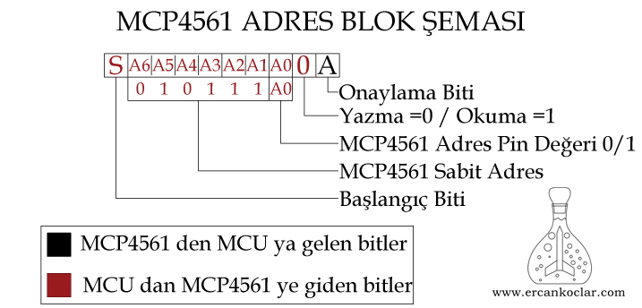
- MCP4561 has 1 address pin (A0). Therefore, this pin can be set to 1 or 0 to define the address. (This means that only 2 MCP4561 devices can be used on the same I2C line.)
- The addressing system, as shown above, is in the format 010111+A0 (standard address+other adsress pins+A0) The section before A0 is fixed, while A0 can be either 1 or 0.
- In the I2C protocol, each operation always begins with a start condition. A 7-bit address + 1-bit operation equals 8 bits of information, which is sent, and an acknowledgment (ACK 1) or non-acknowledgment (NACK 0) signal is received from the MCP4561. This is how the target device is selected for further operations.
- NOTE: In other models of MCP, there may be multiple address pins, but in the example above, the region ‘0101’ is always fixed. However, the MCP4561 does not include A2 and A1 pins, and these are assumed to be ‘1’, with only A0 being variable. If other models have more address pins, the address should be determined accordingly.
MCP4561 Genral Command Transmission System
| General Commands | ||
| 7 bit Command | Function | |
| 100000D | Writes data to the wiper area – Volatile Memory | Expanded Command |
| 110000D | Writes data to the TCON area – Volatile Memory | Expanded Command |
| 1000010 | Increases the Wiper Value | General Command |
| 1000100 | Decreases the Wiper Value | General Command |
- General commands are used to operate on all MCP4561 devices simultaneously on the I2C bus.
- The available operations are limited to those in the table above. Any attempt to perform operations outside of these will result in an error.
- The address must always be “00000000“
- In data write commands, “D” is the 9th data bit. The details will be explained below
- The general command system is divided into two parts
- General Command System
- Expanded General Command System
General Command System
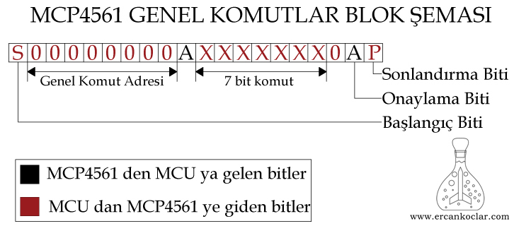
- Only a 7-bit command is transmitted; no data is sent
- Used for increasing and decreasing the wiper value.
- The “0” bit after the 7-bit command is fixed.
Expanded General Command System
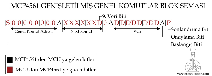
- In the general command system, it is used for writing data.
- Accordingly, data can be written to the TCON and Wiper registers, but these are volatile memory areas. In other words, the written data will be erased when power is lost.
- In this section, there is an additional 9th data bit, and the reason for this is as follows:
- The MCP4561 consists of 257 steps, ranging from 0 to 256.
- Therefore, when setting the resistor value in the MCP4561, a value between 0 and 256 can be input.
- As you’ve noticed, the value 256 doesn’t fit into 8 bits, so a 9-bit space is required.
- For these reasons, if the value 256 is to be written to the Wiper register, the part that overflows into the 9th bit should be appended to the end of the 7 command bits and transmitted.
- Under normal conditions, if the data fits within 8 bits, the 9th data bit should be “0”. Only when sending the value 256, the 9th data bit will be set to “1”, and all other data bits will be “0”. The binary representation of 256 is 00000001 00000000 >(16-bit binary).
MCP4561 Operation Commands
| Operation Commands | |
| Command (binary) | Function |
| 00 | Data Write |
| 01 | Wiper Increase |
| 10 | Wiper Decrease |
| 11 | Read Data |
- The commands provided in this section are specific to each MCP4561, meaning they are valid only for the MCP4561 selected by the address.
- In all these operations, the MCP4561 address must be selected first, followed by the memory address where the operation will be performed.
MCP4561 Data Write Operation
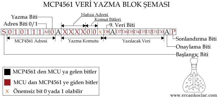
- For the write operation, the address of the MCP4561 on which the operation will be performed is sent first to make the selection.
- The memory address and command for the data write operation are combined. If the value to be written is 256, the D8 bit is set to 1.
- If the data to be written is less than 256, D8 is set to 0, and after acknowledgment, the 8-bit data is transmitted. Otherwise, the 8-bit section will be zero.
- If the operation is to continue without interruption, the Stop-P command is not sent. After acknowledgment, the memory address and command combination are sent again, and data can be written once more.
- When the process is to be finished, it is terminated with a STOP-P signal.
- If data is to be written again after the process is terminated, the MCP4561 must be selected from the beginning.
MCP4561 Data Read Process
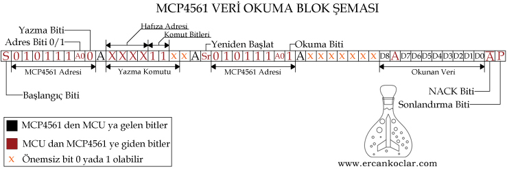
- In the I2C protocol, reading is not as easy and straightforward as writing; it is somewhat more complicated, which can lead to errors in some cases.
- First, the address of the MCP4561 should be selected for writing.
- The RAM address to be read is selected using the read command (binary 11).
- Restart is performed, and this time the address of the MCP4561 should be selected for reading.
- As the clock is sent, data starts to be received. If an ACK is sent at the end of each data packet, the data continues to be received. When a NACK is sent, the communication is terminated, and the process stops with a STOP command.
- As I mentioned earlier, the MCP4561 can accept a value of 256. Here, we also see the D8 bit, which corresponds to the 9th data bit, in case of the value 256. When reading data, the first 7 bits are ignored for this reason. After reading the 8th bit and sending an acknowledgment, the next 8 bits contain the valuable data for us. In total, we are concerned with 9 bits.
- In the read process, when data starts to arrive, as you can see in the diagram above, ACK or NACK signals are sent from our side (MCU) to the MCP4561, unlike in the write process. This happens only when the data starts to arrive, not during the address transmission or other parts.
- At the end of data reading, unless a NACK is sent, data reading will continue. According to the I2C protocol, the MCP4561 will increment its pointer after each read and will read the data at the next address.
MCP4561 Wiper Increase Process
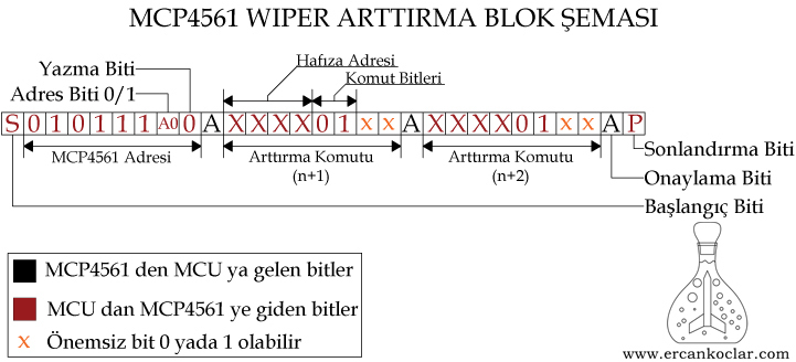
- The wiper represents the middle pin used for adjustment in trimpots. Therefore, the operation here is to increase this adjustment pin inside the MCP4561.
- The MCP4561 system has 257 steps (0-256). Therefore, with each step, there will be an increase or decrease of 39 ohms. (Remember, the trimpot has 3 pins, so the resistance value may increase or decrease depending on where you measure it.)
- In the wiper increase operation, only the data in the volatile wiper memory (00h) can be increased or decreased; this operation cannot be performed in other areas.
- Once the MCP4561’s address is sent, continuous increments can be achieved by sending consecutive wiper increase commands as shown above.
MCP4561 Wiper Decrease Operation
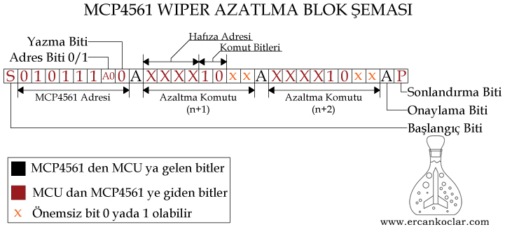
- The wiper represents the middle pin used for adjustment in trimpots. Therefore, the operation here decreases this adjustment pin inside the MCP4561.
- The MCP4561 system has 257 steps (0-256). Therefore, with each step, there will be an increase or decrease of 39 ohms. (Remember, the trimpot has 3 pins, so the resistance value may increase or decrease depending on where you measure it.)
- In the wiper decrease operation, only the data in the volatile wiper memory (00h) can be increased or decreased; this operation cannot be performed in other areas.
- Once the MCP4561’s address is sent, continuous decrements can be achieved by sending consecutive wiper decrease commands as shown above.
MCP4561 Pin Functions
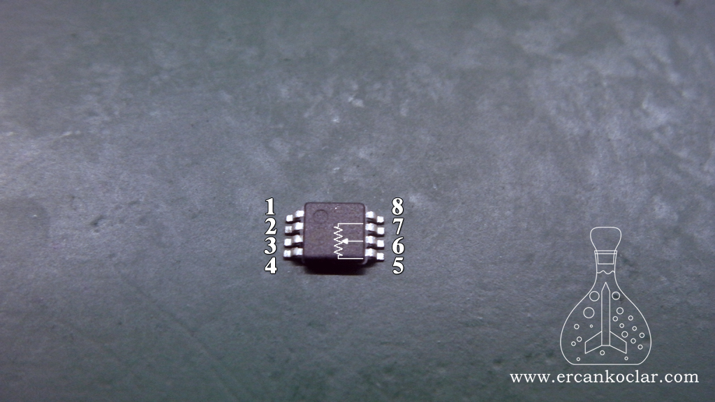
| Pin | Name | Function |
| 1 | A0 | I2C Address Pin |
| 2 | SCL | I2C Clock Pin |
| 3 | SDA | I2C Data Pin |
| 4 | Vss | GND |
| 5 | P0A | Adjustable resistor 1st Pin |
| 6 | P0W | Adjustable resistor wiper pin- WIPER |
| 7 | P0B | Adjustable resistor 2nd Pin |
| 8 | Vdd | Power +1,8V / +5V |
- The WIPER mentioned above and frequently referenced in the library represents the middle pin used for adjustment in adjustable resistors.
- The addressing pin is set to 1 or 0 by connecting it to either +5V or GND, allowing the use of one or even two MCP4561 devices on the same bus.
MCP4561 Digital Trimpot Circuit
- In this section, we will see the necessary basic circuit for the MCP4561.
- It doesn’t require many components, as it is essentially a trimpot.
MCP4561 Circuit Diagram
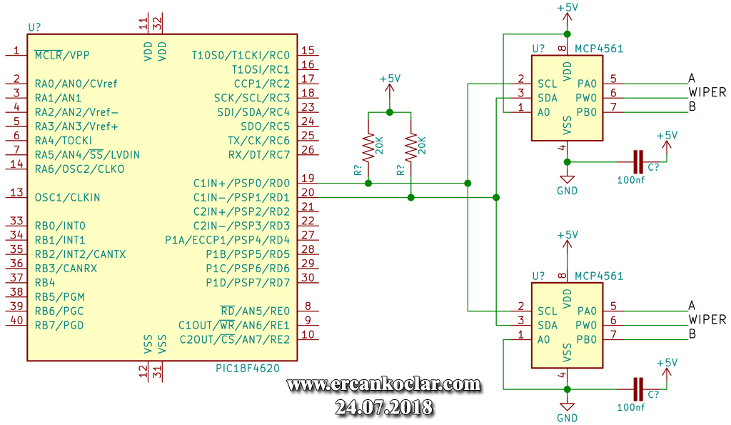
- In the circuit diagram, pay attention to the two address pins of the MCP4561. One is set to “1” while the other is set to “0“
- The I2C lines must be pulled up with 20k resistors.
- The A, WIPER, and B terminals are resistor outputs. They can be thought of as the 1-2-3 pins of a trimpot
Necessary Materials
- MCP4561
- 100nf capacitor
- 20 k resistor – 2 units
- DIP adapter for test circuits
Circuit Construction
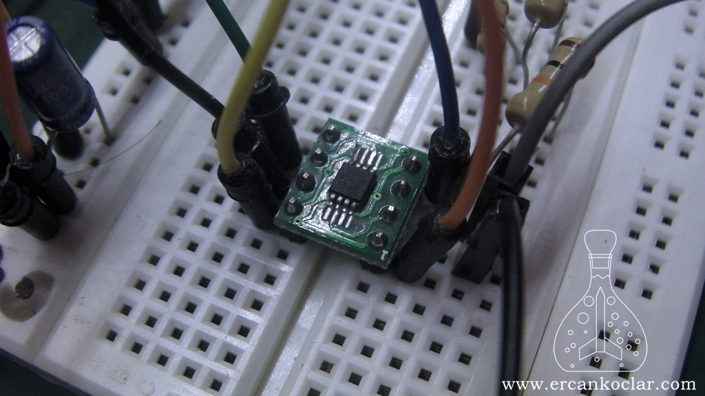
- Since the circuit is simple, I tested it by setting it up on a board
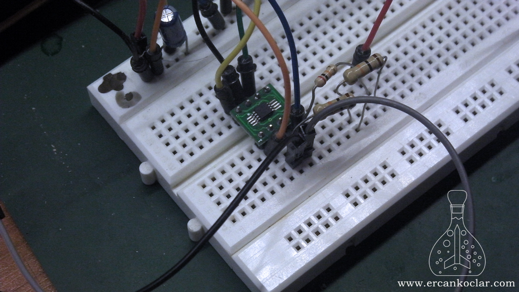
- Using a DIP adapter provides great convenience in test circuits.
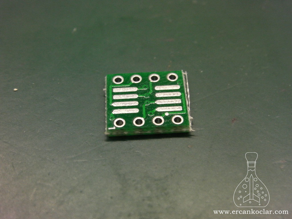
- The MCP4561 has significant advantages in terms of size.
MCP4561 MikroC Library
- The MCP4561 operates with the I2C protocol; therefore, I prepared the library using the I2C protocol I previously wrote. You should download the I2C library from here and include it in your project.
- –
- As we mentioned, the 10k model of the MCP4561 has 257 steps, and each step is 39 ohms
- WIPER functions represent the movement of the middle pin in trimpots.
Functions
- All functions are user functions.
- Some functions were created to provide convenience for the user.
General Command Functions
- The functions in this section allow controlling all MCP4561 devices on the same I2C line simultaneously.
- You can find the commands in the MCP4561.h file.
– MCP4561_GENEL_KOMUTLAR Function
Function: unsigned char MCP4561_GENEL_KOMUTLAR(unsigned char KOMUT)
Purpose: Executes general commands. It performs wiper increment and decrement operations on MCP4561 devices on the I2C bus.
Parameters :
- The command to be executed is written here
How to Use :
MCP4561_GENEL_KOMUTLAR(WIPER_ARTTIR);
Feedback :
- If 1 is returned, the operation is successful.
– MCP4561_GENISLETILMIS_GENEL_KOMUTLAR Function
Function : unsigned char MCP4561_GENISLETILMIS_GENEL_KOMUTLAR(unsigned char KOMUT,unsigned char VERI)
Purpose: Executes general commands. It is used to write to the TCON area and the volatile wiper value of MCP4561 devices on the I2C bus.
Parameters :
- KOMUT : The command to be applied is written here.
- VERI : The data to be written is entered here.
How to Use :
MCP4561_GENISLETILMIS_GENEL_KOMUTLAR(TCON_REGISTER_DEGERI,0b11001100)
Feedback :
- If 1 is returned, the operation is successful.
Operation Functions
– MCP4561_VERI_OKUMA Function
Function : unsigned int MCP4561_VERI_OKUMA(unsigned char MCP4561_ADRESI,unsigned char RAM_ADRESI)
Purpose: Reads data from the specified memory area.
Parameters :
- MCP4561_ADERSI : The address of the MCP4561 to be read is specified. It takes a value of 0 or 1 based on the A0 pin.
- RAM_ADRESI : The memory address to be read is specified.
How to Use :
MCP4561_VERI_OKUMA(0,5);
Feedback :
- Sends the read data as feedback, returning a value between 0 and 256.
– MCP4561_DIRENC_DEGERI_OKU Function
Function : unsigned int MCP4561_DIRENC_DEGERI_OKU(unsigned char MCP4561_ADRESI,unsigned char RAM_ADRESI)
Purpose: Directly reads the resistance value from the specified wiper points.
Parameters :
- MCP4561_ADRESI : The MCP4561 address to be read is specified. It takes a value of 0 or 1 based on the A0 pin.
- RAM_ADRESI : The memory address to be read is specified.
How to Use :
MCP4561_DIRENC_DEGERI_OKU(0,5);
Feedback :
- The data is provided directly in ohms.
– MCP4561_STATUS_OKUMA Function
Function : unsigned char MCP4561_STATUS_OKUMA(unsigned char MCP4561_ADRESI)
Purpose: Reads the status register.
Parameters :
- MCP4561_ADRESI : The MCP4561 address to be read is specified. It takes a value of 0 or 1 based on the A0 pin.
How to Use :
MCP4561_STATUS_OKUMA(0);
Feedback :
- Returns the data read from the status register.
– MCP4561_VERI_YAZMA Function
Function : unsigned char MCP4561_VERI_YAZMA(unsigned char MCP4561_ADRESI,unsigned char RAM_ADRESI,unsigned int VERI)
Purpose: Writes data to the selected memory address.
Parameters :
- MCP4561_ADRESI : The MCP4561 address to be read is specified. It takes a value of 0 or 1 based on the A0 pin.
- RAM_ADRESI : The memory address to be read is specified.
- VERI : The data to be written is loaded into this variable (if writing to wiper registers, a value between 0 and 256 can be used).
How to Use :
MCP4561_VERI_YAZMA(0,5,125);
Feedback :
- If 1 is returned, the operation is successful.
– MCP4561_DIRENC_DEGERI_YAZ_GECICI Function
Function : void MCP4561_DIRENC_DEGERI_YAZ_GECICI(unsigned char MCP4561_ADRESI,unsigned int DIRENC_DEGERI_OHM)
Purpose: Writes the entered resistance value (in ohms) to the volatile resistor area.
Parameters :
- MCP4561_ADRESI : The MCP4561 address to be read is specified. It takes a value of 0 or 1 based on the A0 pin.
- DIRENC_DEGERI_OHM : The desired resistance value is entered in ohms.
How to Use :
unsigned char MCP4561_DIRENC_DEGERI_YAZ_GECICI(0,39);
Feedback: No feedback provided.
– MCP4561_DIRENC_DEGERI_YAZ_KALICI Function
Function : void MCP4561_DIRENC_DEGERI_YAZ_KALICI(unsigned char MCP4561_ADRESI,unsigned int DIRENC_DEGERI_OHM)
Purpose: Writes the entered resistance value (in ohms) to the non-volatile resistor area.
Parameters :
- MCP4561_ADRESI : The MCP4561 address to be read is specified. It takes a value of 0 or 1 based on the A0 pin.
- DIRENC_DEGERI_OHM : The desired resistance value is entered in ohms.
How to Use :
unsigned char MCP4561_DIRENC_DEGERI_YAZ_KALICI(0,39);
Feedback: No feedback provided.
WIPER Functions
– MCP4561_WIPER_BASLANGIC Function
Function : unsigned char MCP4561_WIPER_BASLANGIC(unsigned char MCP4561_ADRESI)
Purpose: This function is called first to perform the wiper adjustment.
Parameters :
- MCP4561_ADRESI : The address of the MCP4561 to be read is specified. It takes a value of 0 or 1 based on the A0 pin.
How to Use :
MCP4561_WIPER_BASLANGIC(0);
Feedback :
- If 0 is returned, the operation has failed.
– MCP4561_WIPER_ARTTIRMA Function
Function : unsigned char MCP4561_WIPER_ARTTIRMA()
Purpose: Increases the wiper by one step.
Parameters: None
How to Use :
MCP4561_WIPER_ARTTIRMA();
Feedback :
- If 1 is returned, the operation is successful.
– MCP4561_WIPER_AZALTMA Function
Function : unsigned char MCP4561_WIPER_AZALTMA()
Purpose: Decreases the wiper by one step.
Parameters: None
How to Use :
MCP4561_WIPER_AZALTMA();
Feedback :
- If 1 is returned, the operation is successful.
– MCP4561_WIPER_SONLANDIR Function
Function : void MCP4561_WIPER_SONLANDIR()
Purpose: Terminates the wiper adjustment process.
Parameters: None
How to Use :
MCP4561_WIPER_SONLANDIR();
Feedback: No feedback provided.
Application of Functions
- In the application section, we will cover writing and increasing the resistance value.
- There are a few important points here.
- The value written to the non-volatile wiper section cannot be increased or decreased; only the value in the volatile wiper section can be adjusted.
- If you want the value written to the non-volatile section to be valid without a power reset, you should also write this value to the volatile section.
//I2C protokolü için pin ayarlamaları
 sbit I2C_SDA at RB6_bit;
 sbit I2C_SCL at RB7_bit;

 sbit I2C_SDA_VERI at LATB6_bit;//27.01.2019 güncellemesi ile eklendi

 sbit I2C_SDA_Direction at TRISB6_bit;
 sbit I2C_SCL_Direction at TRISB7_bit;

void  main()
{

    unsigned int deger=0;
    CMCON=7;

    MCP4561_DIRENC_DEGERI_YAZ_KALICI(0,5000);//5000 ohm yani 5k

    deger=MCP4561_DIRENC_DEGERI_OKU(0,2);

    MCP4561_DIRENC_DEGERI_YAZ_GECICI(0,deger);


}
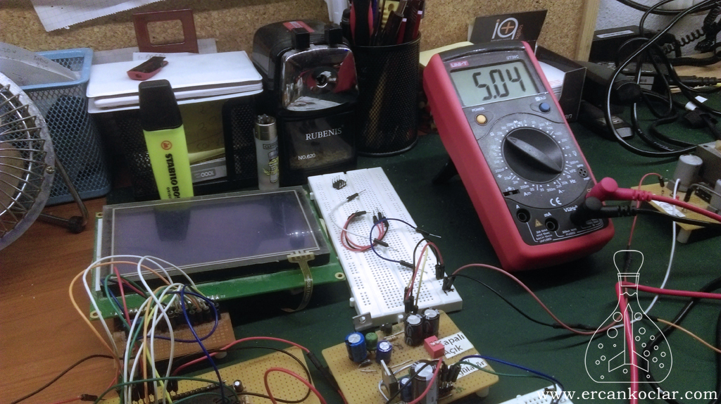
- To explain the example above:
- First, we wrote the value of 5k to the non-volatile wiper area. However, this value will not be 5k until the power is cycled.
- To ensure this, the same value was also written to the volatile wiper area, so the value was subsequently written to the temporary wiper section.
- The purpose of reading the resistance value is to retrieve and read the data previously written to the non-volatile wiper section.
//I2C protokolü için pin ayarlamaları
 sbit I2C_SDA at RB6_bit;
 sbit I2C_SCL at RB7_bit;

 sbit I2C_SDA_VERI at LATB6_bit;//27.01.2019 güncellemesi ile eklendi

 sbit I2C_SDA_Direction at TRISB6_bit;
 sbit I2C_SCL_Direction at TRISB7_bit;

void  main()
{

    unsigned int deger=0;
    CMCON=7;

    MCP4561_DIRENC_DEGERI_YAZ_KALICI(0,5000);

    deger=MCP4561_DIRENC_DEGERI_OKU(0,2);

    MCP4561_DIRENC_DEGERI_YAZ_GECICI(0,deger);


    MCP4561_WIPER_BASLANGIC(0);
    MCP4561_WIPER_ARTTIRMA();
    MCP4561_WIPER_ARTTIRMA();
    MCP4561_WIPER_SONLANDIR();


    deger=MCP4561_DIRENC_DEGERI_OKU(0,0);
    MCP4561_DIRENC_DEGERI_YAZ_KALICI(0,deger);


}
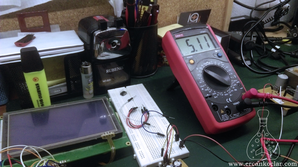
- Above, the 5k value in the volatile wiper area was increased twice, resulting in 5000 + 39 + 39 ohms.
- Then the process was terminated, but to make this increase permanent, the value was read from the volatile memory and written to the non-volatile wiper area. In this way, the two-step increase became permanent.
- The value is shown as 5.04k above. 5.04 x 1000 = 5040 ohms.
- We increased by 2 steps, which means 39 x 2 = 78 ohms.
- 5040 + 78 = 5118 ohms / 1000 = 5.11k, and the measuring device confirms this result.
The Operation Video
Result
- You have learned how the MCP4561 operates. Now you can write your own code or use my library.
- The MCP4561 can be used in many areas and will be especially useful in applications requiring calibration. Additionally, it allows adjustments, such as screen brightness, without opening the circuit enclosure.
- –
- You can ask your questions on the “Q&A” forum.
Library Files
- MCP4565 Digital Trimpot MikroC Library – .mcl – (FREE)
Bağlantıyı Görmek İçin Giriş Yapın ya da Ücretsiz Üye Olun
- I2C MikroC Library – .mcl – (FREE)
Bağlantıyı Görmek İçin Giriş Yapın ya da Ücretsiz Üye Olun
References
PIC
This post is also available in:
![]() Türkçe (Turkish)
Türkçe (Turkish)
