This post is also available in:
![]() Türkçe (Turkish)
Türkçe (Turkish)
- DHT11 Humidity and Temperature Sensor
- DHT11 Working Protocols
- DHT11 Pins Functions
- DHT11 Humidity and Temperature Sensor Circuit
- DHT11 Humidity and Temperature Sensor MikroC Library
- Tutorial Video
- Conclusion
- Kütüphane Dosyaları
- Resources Used
DHT11 HUMIDITY and TEMPERATURE Sensor
- DHT11 can be used to measure air humidity and temperature.
- It can be used in greenhouses.
- It is suitable for non-sensitive humidity and temperature measurements.
Specifications of the DHT11 Humidity and Temperature Sensor
- The positive and negative aspects of the DHT11 can be seen below
- You can evaluate your project based on the following specifications.
| DHT11 Humidity and Temperature Sensor Features | |
| Positive Features | Negative Features |
|
|
- The detailed working features of the DHT11 can be seen in the table below.
| Humidity Measurement Values | ||||||||||||||||
| Parameters | Conditions | Min | Average | Max | ||||||||||||
| Resolution | 1%RH | 1%RH(8 bit) | 1%RH | |||||||||||||
| Repeatability | ±1%RH | |||||||||||||||
| Accuracy |
|
|
|
|
||||||||||||
| Measurement Range |
|
|
|
|
||||||||||||
| Response Time (s) | 1/e(63%)25 °C, 1m/s Air |
6 s | 10 s | 15 s | ||||||||||||
| Hysteresis | ±1%RH | |||||||||||||||
| Long-term Accuracy | General | ±1%RH per year | ||||||||||||||
| Temperature Measurement Values | ||||||||||||||||
| Parameters | Conditions | Min | Average | Max | ||||||||||||
| Resolution | 1 °C ( 8 bit) | 1 °C(8bit) | 1 °C(8bit) | |||||||||||||
| Repeatability | ±1 °C | |||||||||||||||
| Accuracy | ±1 °C | ±2 °C | ||||||||||||||
| Measurement Range | 0 °C | 50 °C | ||||||||||||||
| Response Time (s) | 1/e(63%) | 6 s | 30 s | |||||||||||||
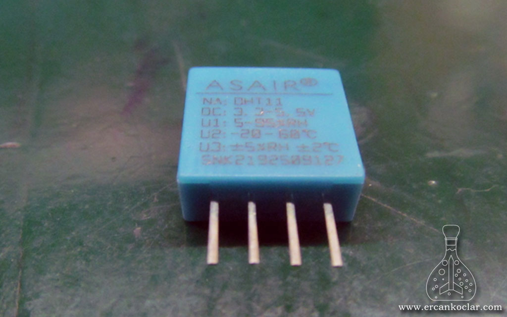
- Some of its features can be seen on the back of the sensor.
DHT11 Working Protocols
- We will see the necessary steps to retrive data from the DHT11
- In thıs section,in order;
- General Working System
- Communication System
- Data Reading System
- We will see the entire communication system and data control
DHT11 General Working System

- As you will see later, the data pin in the DHT11 circiut is pulled up, so the data line is always in a high state
- To communicate with the DHT11, the data pin is first set to 0, then set to 1, and the response is awaited.
- The following 40-bit data contains the humidity and temperature values.
DHT11 Communication System

- Before, I had mentioned that the 1-wire protocol was used.
- Timings are very important in this protocol.
- Accordingly, to communicate with the DHT11
- First, set the data pin to 0 and wait for 18ms.
- After setting the data pin to 1, wait for 40us.
- After that, data is read from the data pin.
- DHT11 pulls the data pin to 0 for 50us
- Then it sets the data pin to 1 for 80us
- When all the above steps are completed, the DHT11 is ready to start sending humidity and temperature data.
DHT11 Data Reading System

- In the 1-wire protocol, we determine whether the received data is 0 or 1 based on the timing, not the logical level. Accordingly;
- If, during the analysis of the 40-bit humidity and temperature data from the DHT11, the logical level remains at 1 for a maximum of 28us and then switches to logical 0, the data is considered as 0.
- Similarly, if the logical level remains at 1 for 70us, then the data is considered as 1.
- As shown above, the DHT11 always keeps the data pin in the logical 0 state for 50 us before sending data.
- In the communication section, all subsequent 40-bit data should be evaluated in this way.
DHT11 Complete Communication System and Data Control
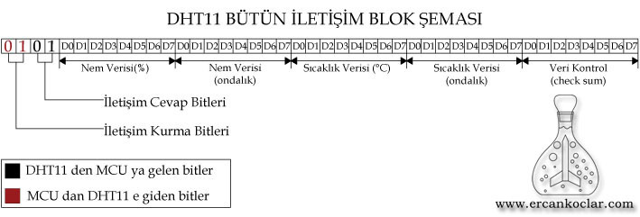
- The complete process with the DHT11 is shown above.
- After the communication process, the following 40-bit data can be grouped as shown below
- The first 8 bits represent the integer part of the humidity value in %RH.
- the second 8 bits represent the decimal part of the humidity value.
- The third 8 bits represent the integer part of the temperature value in °C.
- The fourth 8 bits represent the decimal part of the temperature value.
- The fifth and last 8 bits represent the check-sum for data control.
- If you look at the above tables, the humidity and temperature resolution of the DHT11 is 1, so no decimal data is represented. Therefore, the 2nd and 4th. sections are not considered.
Checking the Accuracy of Data from DHT11 – Checksum
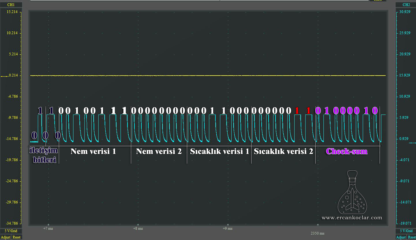
- The checksum is the last 8-bit data.
- To check this, the sum of the 4 pieces of 8-bit data is calculated, excluding the checksum.
- If the result matches the 8-bit checksum, the data is correct; otherwise, there is an error in the data transmission.
- 1.(8-bit data) + 2.(8-bit data) + 3 .(8-bit data) + 4. (8-bit data) = 5 .(8-bit data), which is the checksum
- Crucial: Some sources regarding the DHT11 indicate that the decimal parts should be treated as 0. However, as shown in the oscilloscope image above, sometimes data can appear in places where zeros are expected. These should not be included in the measurement but must be included in the checksum calculation. If these random values are not included in the checksum calculation, the data transmission will be considered faulty.
- Based on the data from the oscilloscope image above
- The humidity data 1 = 00100111 = 39 % RH
- The humidity data 2 = 00000000 = 0
- The temperature data 1 = 00011000 = 24 °C
- The temperature data 2 = 000000 11 = 3 ( This data is not considered while calculating the temperature value.)
- Checksum = 01000010 = 66 ( 39+24+3 =66)
- As a result, as seen, while performing the check-sum process, decimal parts are not considered for humidity and temperature values, but during the verification of data accuracy, all incoming data should be taken into account.
DHT11 Pin Functions
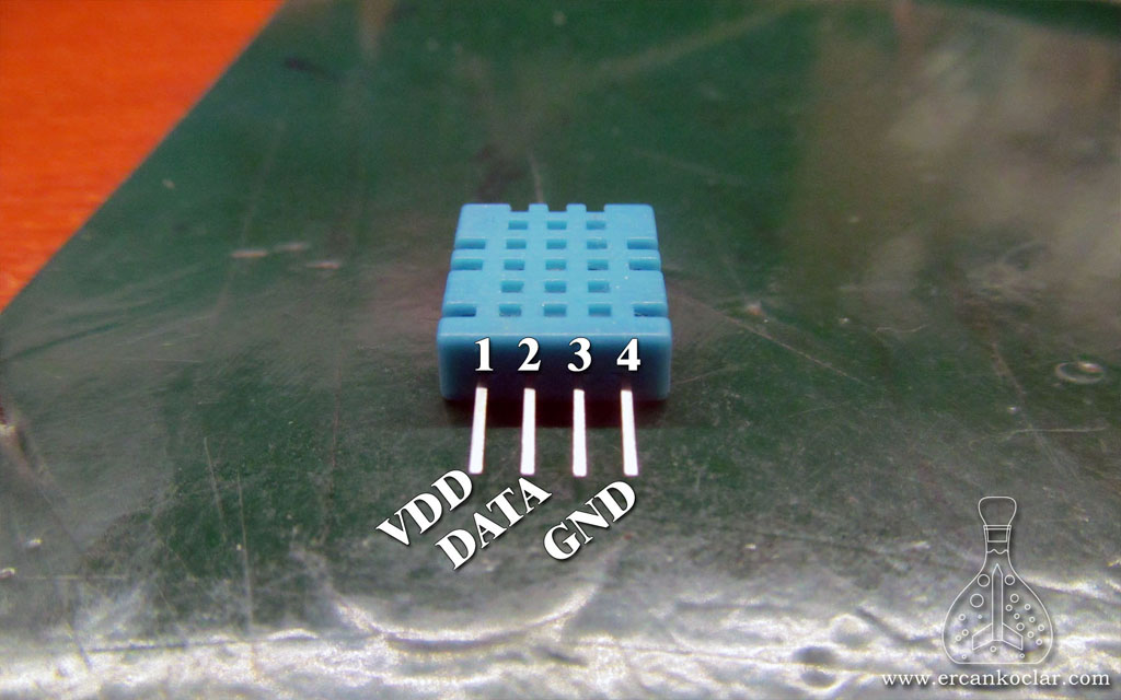
| Pin Name | Function |
| VDD | +5v power supply |
| DATA | Data exchange occurs |
| x | Pin3 is not used |
| GND | Ground |
- In the DHT11, for communication via a single wire, there is only one data pin. There is no clock or similar pin.
DHT11 Humidity and Temperature Sensor Circuit
- In this section, the necessary circuit for the DHT11 humidity and temperature sensor will be shown
- It is stated that the DHT11 humidity and temperature sensor can send data through a 20m long cable, but if the length exceeds 20m, the pull-up resistor needs to be changed. However, I couldn’t find any source that explains how and based on what the new resistor should be calculated. Therefore, I am unable to provide an explanation on this matter.
- For communication over 20m, a +5V power supply is required.
Circuit Diagram
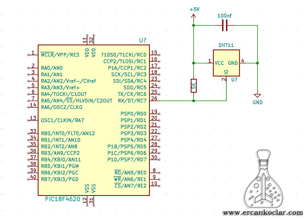
- The data pin must be pulled up with a 5k resistor.
- It is recommended to place a 100nF capacitor between +5V and GND to block interference.
- It gives a digital output, so it can be connected to any input/output pin of the PIC
Necessary Materials
- DHT11 humidity and temperature sensor – 1 pc
- 5k resistor – 1 pc
- 100 nF polyester capacitor – 1 pc
Circuit Construction
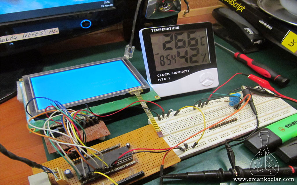
- I set up the circuit on the board.
- I used a 240×128 GLCD to display the results.
- I used a 20 MHz PC oscilloscope to observe the signals.
- I bought a simple humidity and temperature meter to compare the results.
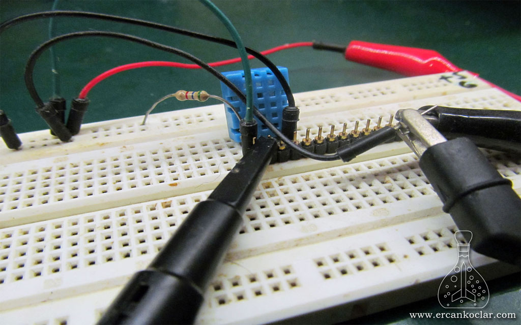
- Close-up view of the DHT11 humidity and temperature sensor
- It has a blue case.
- During the project preparation, I used a resistor with a similar value because I didn’t have a 5k resistor.
- The 100 nF capacitor is not visible because it is behind the sensor.
The DHT11 Humidity and Temperature Sensor MikroC Library
- I wrote a library for the DHT11 in MikroC, but it can be adapted to any environment by using the library as a base. Additionally, it can be used as an example for the ‘1-wire protocol’
- You can purchase the library from the marketplace.
- Since the sensor has a single purpose, the library has been written specifically for that purpose.
Functions
- I did not create a group since it has only one function.
– DHT11_ISI_NEM_VERI_OKUMA The Function
Function : unsigned char DHT11_ISI_NEM_VERI_OKUMA(unsigned char *veri)
Purpose : To retrieve the humidity and temperature data from the sensor.
Parameters :
- *veri : Allows the data to be read externally. In the main program, it must be connected to a char array with 5 characters.
How to Use :
DHT11_ISI_NEM_VERI_OKUMA(data);//Alınan veriler "data" adındaki diziye aktarılır.
Feedback :
- If 1 is received, the data transmission was successful.
- If 0 is received, the data transmission was unsuccessful.
Application of Functions
- We will see how to read the humidity and temperature, and how to verify data security.
- I used my own GLCD library to display the data.
- –
Reading DHT11 Humidity and Temperature Values
- Let’s read the data, perform data verification, and display it on the GLCD.
//GLCD Pin tanımalamarı
char SAPTRIS at trisd;//data portları
char SAPDATA_giris at portd;
char SAPDATA_cikis at latd;
sbit SAP1024_RD at RC1_bit ;       //GLCD RD UCU BAĞLANTI PİNİ
sbit SAP1024_CE at rc2_bit ;       //GLCD CE UCU BAĞLANTI PİNİ
sbit SAP1024_CD at Rc3_bit ;       //GLCD C/D UCU BAĞLANTI PİNİ
sbit SAP1024_RST at Rc4_bit ;      //GLCD RST UCU BAĞLANTI PİNİ
sbit SAP1024_FS at Rc5_bit ;       //GLCD FS UCU BAĞLANTI PİNİ
sbit SAP1024_WR at RC0_bit ;       //GLCD wr UCU BAĞLANTI PİNİ

sbit SAP1024_RD_Direction  at TRISC1_bit;       //GLCD RD UCU BAĞLANTI PİNİ
sbit SAP1024_CE_Direction  at TRISC2_bit;       //GLCD CE UCU BAĞLANTI PİNİ
sbit SAP1024_CD_Direction  at TRISC3_bit;       //GLCD C/D UCU BAĞLANTI PİNİ
sbit SAP1024_RST_Direction at TRISC4_bit;      //GLCD RST UCU BAĞLANTI PİNİ
sbit SAP1024_FS_Direction  at TRISC5_bit;       //GLCD FS UCU BAĞLANTI PİNİ
sbit SAP1024_WR_Direction  at TRISC0_bit;       //GLCD FS UCU BAĞLANTI PİNİ

//DHT11 Pin Tanımlamaları
sbit DHT11_DATA at RC7_bit;
sbit DHT11_DATA_Direction at TRISC7_bit;


void  main()
{
    unsigned char veri[5];//verinin atanacağı dizi
    unsigned char deger;
    char txt[15];
    ADCON1=0b00000001;
    CMCON=7;
    SAP1024_INIT(240,128,6);


    //veriler ekranda daha anlamlı gözükebilmesi için başlıklar oluşturulur
    SAP1024_YAZI_YAZMA(32-9,10,"NEM DEGERI:%");
    SAP1024_YAZI_YAZMA(36,12,"'C");
    SAP1024_YAZI_YAZMA(32-9,12,"ISI DEGERI:");

  while(1)
    {
      do{
         deger= DHT11_ISI_NEM_VERI_OKUMA(veri);
         delay_ms(6500);}// DHT11 tepki süresi 6-10 saniye arası oldugundan 6,5 saniyede 1 kez veri alınır.
      while(deger!=1);//veri doğruluğu kontrol edilir veriler doğru gelmediği müddetçe döngüde kalır

      WordToStr(veri[0],txt);//nem verisi stringe çevirilir
      SAP1024_YAZI_YAZMA(32,10,txt);
      SAP1024_YAZI_YAZMA(32-9,10,"NEM DEGERI:%");

      WordToStr(veri[2],txt);//sıcaklık verisi stringe çevirilir
      SAP1024_YAZI_YAZMA(31,12,txt);
      SAP1024_YAZI_YAZMA(36,12,"'C");
      SAP1024_YAZI_YAZMA(32-9,12,"ISI DEGERI:");

    }

}
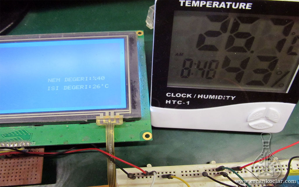
- An infinite while loop was created above to continuously read.
- A do-while loop was created inside the while loop, and a 6.5-second delay was added.
- The DHT11 has a response time between 6 and 10 seconds, so the goal was to retrieve data every 6.5 seconds.
- The other parts were written to convert the data into strings and to make the data appear more meaningful on the screen.
- We stored the data received from the DHT11 in the array ‘veri[5]’. Accordingly
- veri[0]=the humidity data
- veri[2]=the temperature data
- veri[4]=It carries the checksum data.
The Operation Video
Result
- We have examined the working conditions, circuit diagram, and library of the DHT11 humidity and temperature sensor.
- It can be used for humidity and temperature measurements, especially in plant cultivation environments.
- Remember that when the sensor is enclosed, the perforated part must remain outside.
- The position of the sensor is also quite important in humidity and temperature measurements. Elevated central points will provide more accurate results.
- Remember that humidity and temperature measurements are inseparable. Humidity measurement in an environment becomes meaningful when combined with temperature measurement.
- You can ask any questions you have in the ‘Q&A‘ forum.
Library Files
- DHT11 Humidity and Temperature Sensor MikroC Library – OPEN SOURCE – (PAID)
- DHT11 Humidity and Temperature Sensor MikroC Library – .mcl – (FREE)
Bağlantıyı Görmek İçin Giriş Yapın ya da Ücretsiz Üye Olun
References
This post is also available in:
![]() Türkçe (Turkish)
Türkçe (Turkish)
